

ALLOWS MANUAL INTERFACE WITH NAKED BMPCC4K
The new and improved rigid PCB construction of the BMPCC4K extensions means more consistent manufacturing processes, better quality control, and most importantly, higher reliability out in the field with every day use. This PCB connects to the record, on/off, and LED indication circuits. Exposed solder pads are available for installing larger tactile buttons if this is desired or for remote recording via the flight controller.
Features
- Rigid 1mm PCB construction
- Long life micro switches
- LED status and record indicators
- FFC cable interface
- Solder pads for REC and ON/OFF
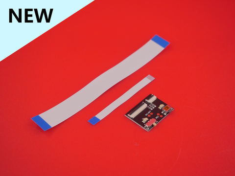
Includes
- 1X Top Buttons PCB Assembly
- 1X 22-pin x 100mm FFC cable
- 1X 8-pin x 50mm FFC cable
Top Buttons Installation for Pigeon 3.0 Cage
The rigid PCB Top Buttons assembly is very similar to the original FPC design, but requires you to utilize some origami skills to fold the FFC cables down nice and flat.

First use double-sided mounting tape to adhere the PCB to the empty space on the camera motherboard. Align the bottom left corner of the PCB with the corner of the motherboard.
If you plan to use the tactile REC and ON/OFF switches, solder the two wire leads to the exposed pads. The red momentary switch goes to the REC pads and the toggle switch goes to the ON/OFF pads. The wire order does not matter for either of these switches. Solder them in a way to avoid the FFC cables as much as possible.
Then insert the 22-pin FFC cable into the left connector as shown above and lock down the black latch.

Next insert the othe rend of the cable into the 22-pin connector on the PCB and lock down the black latch.

Then fold and crease the FFC cable so that it lays flat. Don't worry about breaking the cable, folding it once won't break the circuits.

The tally 8-pin FFC able is a bit more tricky. First insert one end into the small PCB connector and lock down the black latch.

Then fold it to the right as shown above.
 Then fold the other end downward so that it is in-line with the tally connector on the motherboard.

Fold the end back up so that it is aligned with the connector opening.

Insert this end into the connector and lock down the connector latch.

The PCB extension adapter comes with a 3D printed shoulder washer/spacer and stainless steel washer plus hex nut. These are necessary for locking the PCB rigidly to the camera motherboard without putting stress on either PCB, but ensuring that the adapter stays connected and secured to the main camera board.

For Pigeon 3.0 cage owners, installation order of the hardware is shown in the above photo with the main camera PCB going in between the black 3D printed shoulder screw and the M2 hex nut

Tighten the LCD extension PCB to the camera motherboard with the screw assembly so that the 3D printed spacer goes between the PCB extension and the camera motherboard. After tightening the M2 hex nut you can install the original silicone tubing spacer.


Check the image above for proper order and alignment of the hardware bits. The 3D printed shoulder washer is in between there, but not visible due to the shadows.


Next up is the monitor extension PCB! Use two small strips of 3M VHB mounting tape and stick them on the back of the PCB. You can use any other strong double sided acrylic foam-based tape that is about 0.5mm thick. Align the monitor extension PCB with the back of the LCD and stick it down and connect all the plugs. NOTE the above image is the new version of the LCD case which uses 1mm carbon fiber side plates to secure the connector plug in place to prevent stress on the LCD when mating the connectors.

If you have the Pigeon 3.0 cage LCD case you will need to 3D print a TPU brace that slides and clicks around the connector and provides support for the plug. You can find the STL for that HERE. Download the "PCB Brace V5" part file.


After 3D printing your PCB brace you must use side cutters to trim off the bridging filament that supports the latching clip so that you can fully insert the brace and latch it into place behind the connector edge to lock it.

After adhering the the monitor extension PCB to the back of the LCD and connecting the ribbon connectors, slide the TPU PCB brace onto the connector until the internal latch engages and clicks into place. You may not hear a click since it is TPU, but you can tell visually when the bump is gone and the surface is flat.